Visiooimage offers a range of individual components and products to help you create a tailored IRT inspection solution. Please also see our solutions section. If you’re unsure what suits you, please contact us.
PN# PL-C-V-H
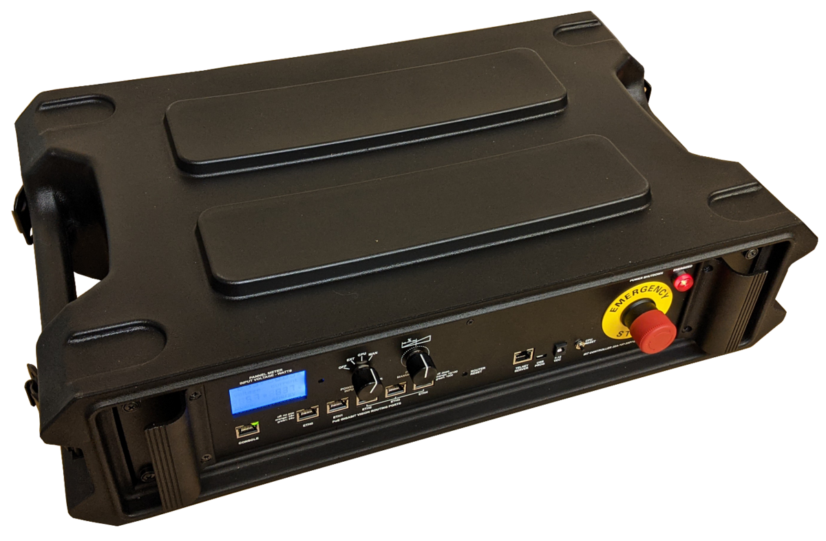
Description: This IR Thermography Controller is designed for halogen heating applications (lock-in modulation, step or pulsed heating). It supports communication with industrial PLCs and robots, and can trigger xenon flash generators. Integrated Ethernet ports and a router enable concurrent communication between cameras, the acquisition PC, and any LAN network. Control is accessible via Ethernet (Telnet).
Specifications: IRT Controller for halogen thermal excitation
- Digital I/O Controller for IR Sources (flash control, lockin modulation, linear heater). Control by Ethernet (Telnet)
- Daisy chainable with extra units if more power is needed.
- PoE 5 ports switch/router
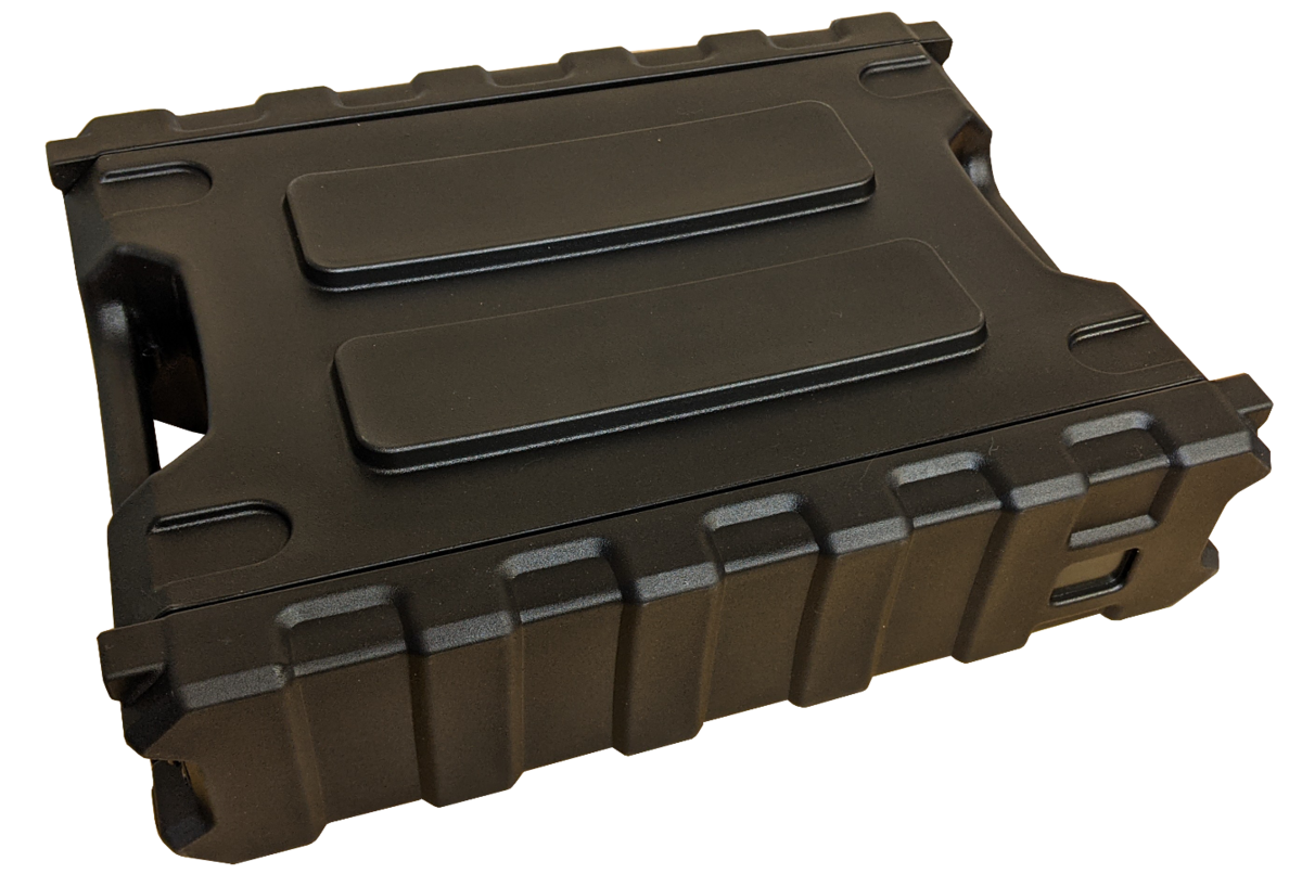
- Rack mounted, 2U, rugged casing
Weight including the rugged mil. casing and caps, no cable: 24.5 lbs (11.1 kg)
Size of the rack unit alone (depth x width x height): 12’’ x 19'' x 3.5’’ (30.5 x 48.3 x 8.9 cm) or 2U rackmount thick
Overall size in the rugged mil. casing with both caps closed (depth x width x height): 17’’ x 23’’ x 6’’ (43.2 x 58.4 x 15.2 cm)
Technical Notes:
The IRT controller is meticulously designed to offer precise control and effortless integration of devices in Infrared Thermographic Testing setups. It serves three main functions:
• It includes an internal voltage generator for resistive loads (typically used for halogen heating) with a stable VAC output. This output can be easily fine-tuned and dimmed to cater to resistive loads, including halogen and IR lamps.
• The control signal outputs of the IRT controller enable efficient management of its internal generator for resistive loads (halogen) or other generators like inductive heating generators, flash heating generators, other connected IRT controllers in series, or any devices that accept 0-5V controls.
• Its capabilities extend to reading and writing on input/output ports, facilitating communication with industrial PLCs and robots. The presence of a router with Ethernet ports ensures concurrent communication between cameras, acquisition PC, and any LAN network.
Practical Examples of IRT Controller Applications:
Utilizing the internal generator for resistive loads (halogen heating):
◦ Initiating lockin modulation with specified durations and frequencies.
◦ Activating step or pulses for designated time intervals.
◦ Exerting control over another IRT controller in slave mode to synchronize and provide additional heating energy when necessary.
◦ Setting the intensity of resistive impedance excitation sources, like halogen/IR lamps, with input voltage fluctuation stabilization (120-240 grid). This can be achieved:
▪ Manually via a knob
▪ Remotely through Telnet commands from any Telnet client
▪ Using an external proportional 0 to 5 V signal.
Controlling a secondary external generator:
◦ Initiating flash pulses through Telnet commands (flash generator required)
◦ Controlling the power of an induction generator through Telnet commands (induction generator required)
Controlling the internal or an external generator:
◦ Simultaneously starting/stopping heating methods and camera acquisitions using Telnet commands. Telnet commands can be programmed using most languages like Matlab or Python.
◦ Creating sequences of functions, such as listening to events on I/O ports to read codes sent by a PLC. Based on the received event and code, the heating can be initiated at a specific power level, followed by camera acquisition and assignment of an identification code to the acquired sequence.
◦ Establishing a connection between the IR camera, the internet, and the acquisition PC through the internal router.
◦ etc.
We encourage you to explore these functionalities to enhance your Infrared Thermographic Testing procedures. If you have queries or require further guidance, please don't hesitate to reach out.
Real-time Voltage Fluctuation Compensation: The phase shift driver detects voltage variations in the 120-240VAC input. These variations result from both normal power grid fluctuations and local voltage changes due to the starting and stopping of various loads around the IRT controller. When the output power is set to less than 100%, the driver calculates how the phase shift should be adjusted to increase or decrease the output voltage in response to decreases or increases in the input voltage, respectively, in order to maintain constant power output. However, it may not fully compensate for a substantial drop in input voltage. The compensation voltage feature is inactive when the dimmer is set to 100%, so working slightly below this threshold is advisable. Line compensation voltage is particularly interesting for halogen heating, as even minor fluctuations might not be visible to the naked eye but can be detected by the IR camera. These fluctuations degrade the probability of detection (POD) or contrast-to-noise ratio (CNR) for potential defects. This becomes even more crucial for line scan applications.
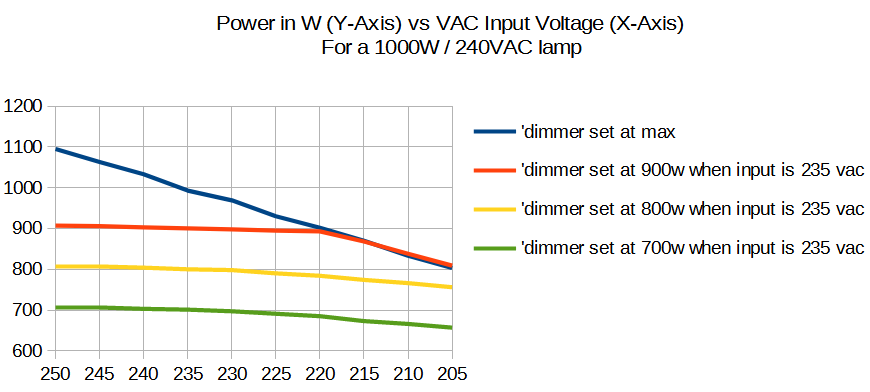
The dimmer was adjusted at 1000W (100% power, with compensation inactive), 900W, 800W, and 700W at 235VAC. The curves illustrate the actual wattage drawn as the voltage varies from 205 to 250VAC
No Hysteresis Effect: Unlike standard dimmers, the phase shift driver does not exhibit a hysteresis effect. When the controller is turned On, then Off, and then On again with a load like a halogen lamp set to low power, it will resume at the same power level as its previous initial On state. This ensures a consistent and controlled power level over time.
Types of Loads to Connect to the Controlled Power Output of the IRT Controller:
Only resistive loads should be connected to the IRT controller's power outputs. Examples of resistive loads include:
• Infrared lamps
• Halogen lamps
• Standard lamps
• Resistors
• Conventional heaters
• Most dipole components with a resistive impedance – i.e. little to no reactive impedance, such as inductors and capacitors.
Temperature Control: The IRT controller is not designed to function as a temperature regulator or thermostat on its own. It does not sense temperature or operate in a closed-loop or feedback control mode. However, if required, end-users can technically achieve this through the I/O ports.
Operating Modes:

For a detailed explanation of operating modes,
please refer to ‘Resources > Technical IRT Tutorial’
PN# PL-C-V-IN
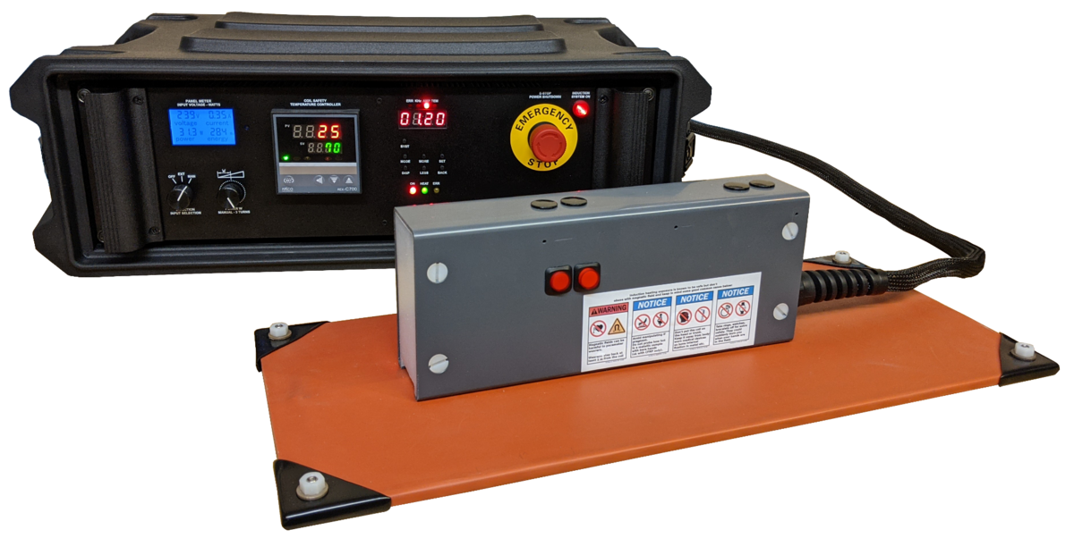
Description: This induction controller uses eddy current heating for the non-destructive testing of metallic plates by thermography. It is particularly effective at detecting hidden corrosion on the reverse side, or corrosion beneath insulating layers on the front side, by heating the affected area from within. This technology also works on Carbon Fiber Reinforced Polymer (CFRP) materials.
Specifications: Induction controller/generator and coil
Inductive source 2kW, 240VAC, Power adjustable 20-100% stepless manual or 0-5V control. Frequency adjusted in real time by automatic tracking control. Ultra low inductance coil. Start time < 1 s. Rack mounted, rugged casing
Technical Notes: The induction controller utilizes eddy current heating to warm electrically conductive materials, including steel, stainless steel, titanium, and Inconel (nickel-chrome-based superalloys). It also effectively heats carbon composite materials like CFRP. This internal heating method is ideal for active IRT thermography, enabling the detection of defects such as delaminations, inserts, impacts, and corrosion.
The system will not heat isolating or non-electrically conductive materials like plastic, glass fiber, or wood. Conversely, highly conductive materials such as copper and aluminum will exhibit minimal or no heating due to their low electrical resistance.
The induction system offers versatile control options. Its control signal output can manage additional heating generators (inductive or halogen) in series, or any device accepting 0-5V control signals. It can also be remotely controlled via an external 0-5V signal from a PLC, IRT controller, or signal generator.
Applications of the Induction Controller
Manual Inspection: Heat a conductive plate by manually scanning the coil across the surface
Automated Line Scanning: Integrate with a robot or gantry system for continuous inspection of long samples.
Synchronized Heating: Control a second induction controller in slave mode to provide additional heating power as needed.
Remote Control (with Halogen IRT Controller): Utilize Telnet commands from any Telnet client to:
Operating Modes:

For a detailed explanation of operating modes,
please refer to ‘Resources > Technical IRT Tutorial’
Further Information
- Resources > Infrared Thermography Testing Using Inductive Heating
- Case Study 1 (PDF): Detecting hidden corrosion on the reverse side of a steel plate.
- Case Study 2 (PDF): Identifying steel slab corrosion beneath bituminous underlay and vinyl tiles.
- Case Study 3 (PDF): Detecting steel corrosion on military defense vessels through paint and insulating layers.
PN# PL-H-V-HS1
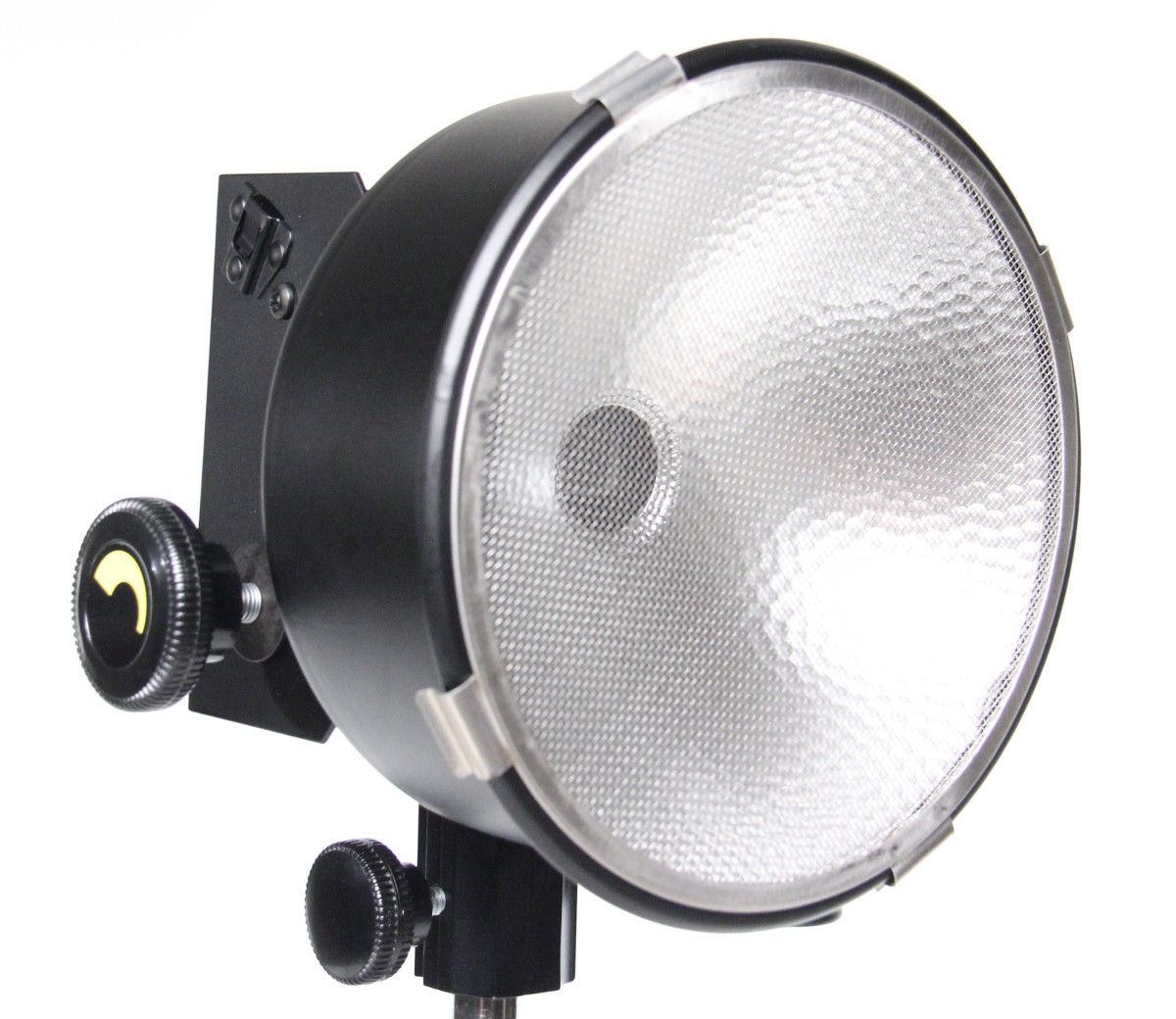
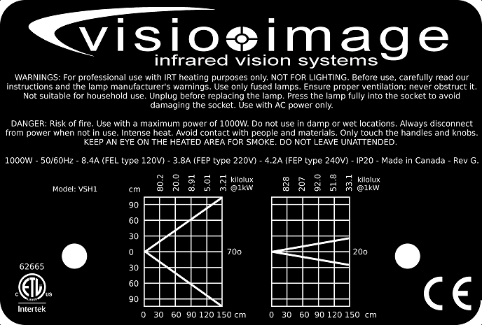
Description: Radiative heating spotlights are suitable for pulsed thermography, delivering higher energy pulses than flash lamps. This makes them ideal for deeper inspections of thicker plates — up to 5 mm or even 10 mm if inspection can also be performed from the back side. They also support step and lock-in heating techniques.
Specifications: Radiative heating spotlights, 1kW. Features a lens-free design for maximum energy transmission and a non-crossover beam. Beam angle adjustable from 20° to 70° using a manual knob, equipped with an FEL type lamp (8:1 focus ratio). Constructed with aluminum and steel, includes a 16' (4.88 m) #16/3 cable. Compatible with 5/8" (1.59 cm) studs. Illuminance ranges from 3208 lux at 1.5 meters with a 70° beam to 33.1 klux with a 20° beam using a 1000W lamp.
Weight (excluding cable): 2.8 lbs (1.3 kg); Weight (with cable): 3.6 lbs (1.6 kg);
Box weight: 4.25 lbs (2.0 kg).
Dimensions: 8.75 x 7 x 8.25" (22.2 x 17.8 x 21 cm).
Operating Modes:

For a detailed explanation of operating modes,
please refer to ‘Resources > Technical IRT Tutorial’
Description:
Flash lamps are used for pulsed thermography, delivering a brief, high-intensity heat pulse to the sample for inspection. They are ideally suited for thin composite panels up to 2mm thick. For thicker panels, pulsed or step halogen heating with an IRT controller is recommended. Flash lamps and generators are characterized by their output energy, commonly ranging from 1-10kJ per head for IRT applications.
Specifications:
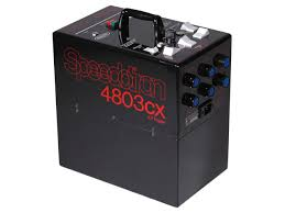
Generator PN# PL-F-S-G48:
Flash generator with 4.8 kJ or kWs energy, compatible with 115V or 230VAC. Can be used in pairs to power a single 9.6 kJ head. Adjustable power levels from Full to 1/8, with a recycle time of 4 seconds. Units can be synchronized using a 1/4" (6.35 mm) jack plug.
Dimensions: 9 x 14 x 14" (22.8 x 35.5 x 35.5 cm). Weight: 43 lb (17.2 kg);
Box weight: 45.90 lb (20.9 kg), dimensions: 16 x 16 x 16 (40.6 x 40.6 x 40.6 cm)
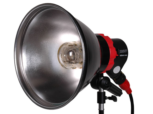
Flash Head PN# PL-F-S-H48:
Flash head 4.8kJ. Flash duration: 1/175s at 4.8kJ, 1/300s at 2.4kJ, 1/500s at 1.2kJ, 1/900s at 0.6kJ, 1/1425s at 0.3kJ. Variable beam. Include 20' (6m) detachable head cable; reflector 11.5’’; Noiseless Fan cooling. Fixture Mount 5/8" Receiver. Casing high glass-fill nylon.
Dimensions 9 x 11.5" (22.8 x 29.2 cm) Including Reflector. 11 lb (5 kg) Including Cable, Reflector.
Package w/ 1 unit: 10.4 lb, 17.6 x 12.6 x 12.5"
Package w/ 2 units: 23.30 lb 14 x 14 x 36’’
Operating Modes:

For a detailed explanation of operating modes,
please refer to ‘Resources > Technical IRT Tutorial’
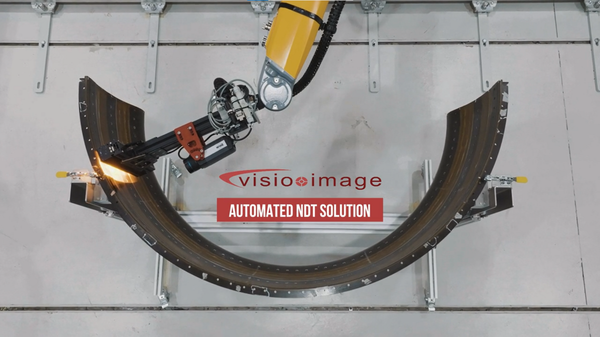
Inspection of a Safran jet engine component—a casing ring (virole)—in a production environment.
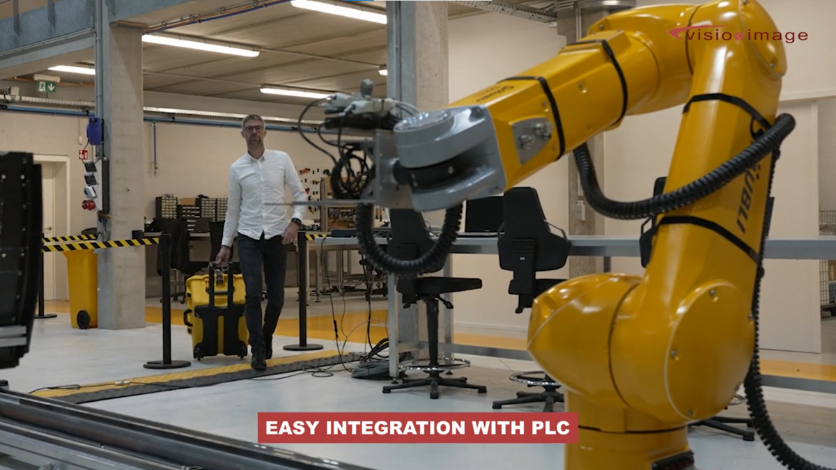
Integration with a robot controller or PLC. Performs exceptionally well when mounted on an XY table or gantry system for planar surface inspection.
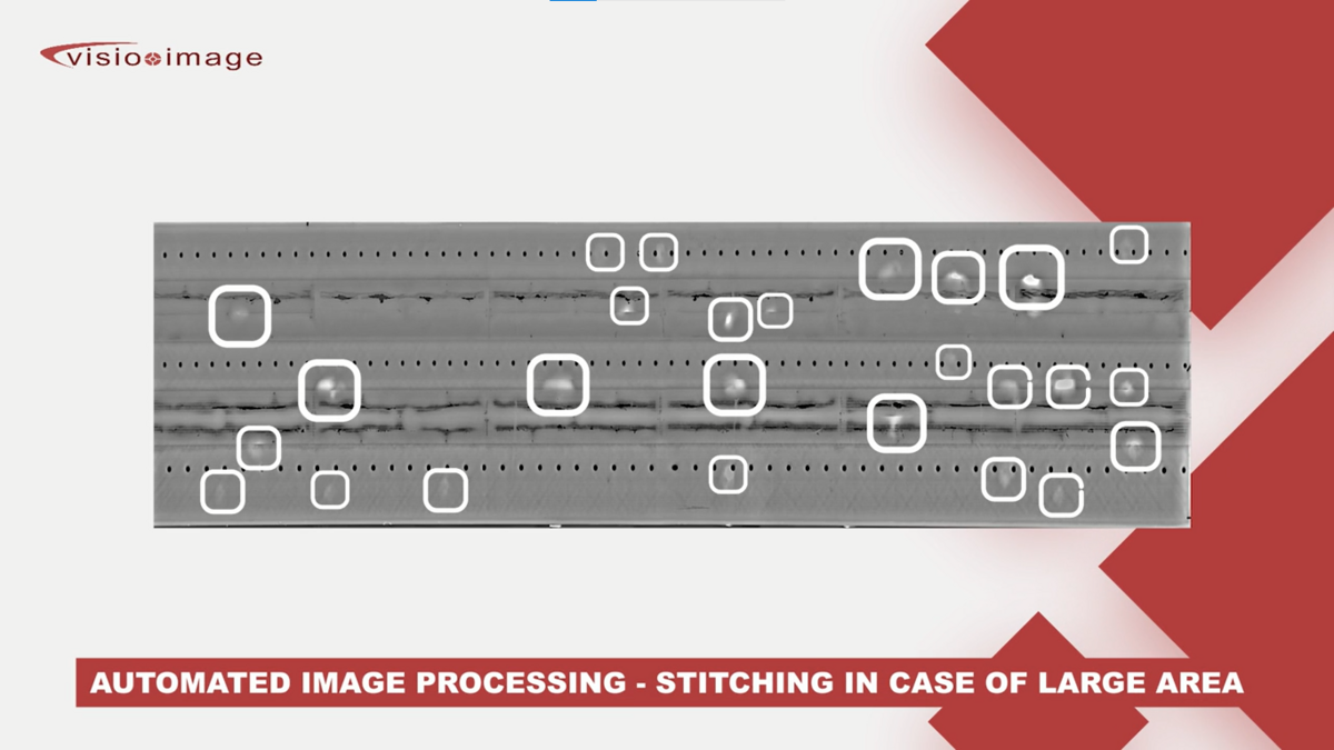
Automatic stitched band result demonstrating large-area inspection capability, showing defects.
PN# PL-LS-V-H
Description: The linescan head is designed for inline inspection of parts in continuous movement on conveyors. It can also be integrated and moved with X-Y/CNC tables, gantries, or robots to inspect very large or curved fixed parts. This system utilizes radiative heating and delivers excellent Probability of Detection (POD) results.
Specifications: Linescan head, vented. Line of heat (net): 27 cm. Bracket to support IR Camera. Inspection speed 0.2 to 1.6 m²/min.
Main arm length, extruded aluminum 50cm long * 45 mm * 90 mm
Overall mounted: 5.0kg, 65 cm height x 37 cm wide x 18 cm thick w/o camera (20 cm thick with camera A655SC)
Box: 21’’ * 4.5’’ * 4.5’’
Operating Modes:

For a detailed explanation of operating modes,
please refer to ‘Resources > Technical IRT Tutorial’
PN# PL-S-V-IV
Description and Specifications:
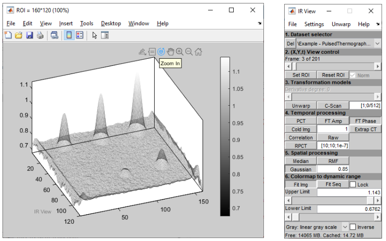
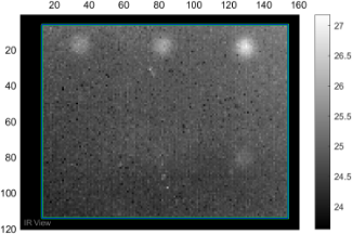
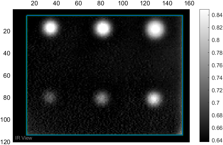
IR View is an IRT Thermography software for IR acquisition processing and defect enhancement in 8 bits, 16 bits or floating point format. Process records of IR sequences of images. Transformation models (C-Scan, Unwarp, and Polynomial Interpolations). Temporal processing (FFT, PCT, DAC/Extrapolated Contrast, Correlation, RPCT, Cold Image). Spatial processing (Median, Gaussian, RMF). Support for multiple native infrared camera formats. Standalone application or integration with Matlab environment. Multi-core CPU support for faster parallel computing.
Technical Notes
Example of processing:
IR View is a software designed for browsing and processing infrared sequences of images for non-destructive testing using infrared thermography (IRT). While relatively simple, it is efficient for both basic and advanced IRT tasks.
The software was originally developed in 1999 for internal use in NDT/IRT research at Laval University in Quebec, Canada, at the MIVIM Laboratory under the direction of Professor Xavier Maldague.
IR View is compatible with almost any RAM and CPU configuration, but the ability to process larger sequences is highly dependent on the computer's RAM and processing power. While there is no specific limit to the computer's configuration, larger sequence files can consume a significant amount of storage and computational power, both in terms of CPU and RAM. A higher-end configuration is typically more suitable for processing larger sequences. For example, a 24GB RAM, 0.5TB SSD drive, and 6-core CPU-based PC or better is well-suited to process 1GB sequences of IR images. Additionally, IR View uses parallel computing, which means that multicore CPUs (each core with its own separate FPU) provide an interesting advantage.
IR View is a Matlab-based software that is provided in two versions:
Both versions are identical in functionality, and the only difference lies in the environment in which they run.
When starting IR View, two panes or windows are displayed as shown above. The left pane displays the IR images or the sequence and processed results. The right pane serves as the IR View control pane.
The control pane is divided into 6 sections, which are the ordered steps through which an image or sequence of images is processed before its output is displayed. These 6 functions are:
The six functions in the control pane are performed in this specific order from 1 to 6. It means that changes made to options in a given step affect all steps below but not those above.
The current formats implemented and recognized are:
'*.irb', 'Jenoptik (*.irb)';
'*.mat', 'Matlab MAT-files (*.mat)';
'*.tif', 'Multiframe TIFF (*.tif)';
'*.hcc', 'Telops (*.hcc)';
'*.sfmov', 'FLIR (*.sfmov)';
'*.ravi', 'Micro-Epsilon | Optris (*.ravi)';
'*.seq', 'FLIR (*.seq)';
'*.fcf', 'FLIR (*.fcf)';
'*.csv', 'Comma-Separated Values (*.csv)';
'*.txt', 'Separated Values with any delimiter (*.txt)';
'*.ats', 'FLIR (*.ats)';
'*.csq', 'FLIR (*.csq)';
'*.jpg', 'FLIR (*.jpg)';
'*.xvi', 'Xenics (*.xvi)';
For the Following Operating Modes:

For a detailed explanation of operating modes,
please refer to ‘Resources > Technical IRT Tutorial’
Further Information:
- Resources > Technical IRT Tutorial
- Solutions > InfraPAK II Solution
Download IR View
Please contact us for a fully functional demo (limited in size of sequence) version of IR View.
PN# PL-S-V-IS
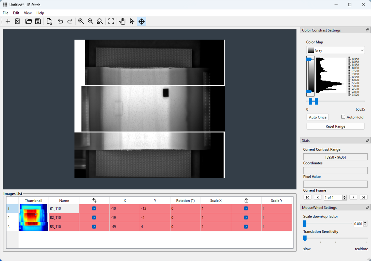
Description: IR Stitch is a software solution for stitching together infrared (IR) tiles or bands, typically acquired using the software 'IRT Bot'. It’s designed for cases where a part is too large or complex to be inspected in a single scan.
Technical Notes: For parts exceeding the inspection area, multiple sections or tiles are acquired. IR Stitch software assembles these tiles – whether processed or raw – in the native 16-bit format to create a complete image of the entire part. Individual tiles can be independently rescaled along the X or Y axis to correct image ratios, rotated from 0 to 360 degrees, and positioned along the X and Y axes within the global plane for accurate recomposition. The initial stitching process is performed manually, then the configuration (scales, angles, position) can be saved and reapplied to subsequent tile sets from other similar inspections. IR Stitch offers both a graphical user interface (GUI) and command-line operation for automated image recomposition. It is commonly used in conjunction with IRT Bot software for automated or robotic inspections.
For the Following Operating Modes:

For a detailed explanation of operating modes,
please refer to ‘Resources > Technical IRT Tutorial’
Further Information:
- A demo version of IR Stitch is available upon request. This version provides access to all functions except image saving.
PN# PL-S-V-IB
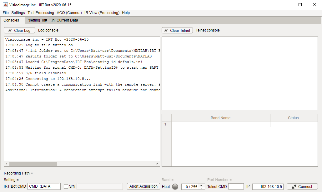
Description: IRT-Bot is software that manages automated inspections by acquiring and collecting data. It processes this data and can utilize IR View for image and sequences processing. Additionally, IRT-Bot adjusts heating power (halogen or inductive) and recomposes images using IR Stitch (optional).
Technical Note: Automated inspections utilize an actuator – such as a gantry, conveyor, CNC machine, or robot – to move either the IRT system or the part being inspected. A Programmable Logic Controller (PLC) transmits the part number and position data to the IRT (halogen) Controller via I/O ports. IRT Bot connects to the IRT Controller via TCP/IP and monitors PLC signals from the actuator. It initiates and stops data acquisition, adjusts heating power as needed, processes the data, and recomposes images from multiple tiles or bands with IR Stitch.
Typically used in conjunction with IR Stitch, IR View, Linescan Head, and IRT Controller
For the Following Operating Modes:

For a detailed explanation of operating modes,
please refer to ‘Resources > Technical IRT Tutorial’
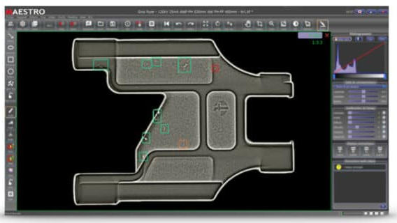
PN# PL-S-X-MV
Description: Maestro Viewer is a reporting tool designed for creating standardized and uniform reports, with integrated commenting and annotation capabilities. It streamlines the interpretation of defects in both digital X-ray and IRT thermographic images. The software provides real-time image enhancement filters to improve clarity, contrast, defect detection, denoising, edge enhancement, and pseudo-3D visualization.
For the Following Operating Modes:

For a detailed explanation of operating modes,
please refer to ‘Resources > Technical IRT Tutorial’
Further Information:
Please contact us for a demo version.
Technical notes:
An Inspection Reference Panel (IRP), sometimes also called a Reference Coupon or Calibration Panel, is a standardized sample used for nondestructive testing (NDT) of composite materials, particularly in infrared thermography and other inspection methods. It contains known, arbitrary, and verified defects with precise CAD design and clear specifications in size and depth, positioned at known locations. These defects are typically validated and certified by the IRP manufacturer.
Purpose of an IRP:
Common Features of an IRP:
3 types of Inspection reference panels are offered
1. Step Wedge with Flat Bottom Holes (FBH) simulating delaminations
PN# PL-IRP-AL-SW

CAD of the 350 x 180 mm IRP
Size 350 x 180 x 12 mm
6 steps thickness from 2.24 mm (8 plies) to 11.2mm (40 plies). Each step has 6 FBH as follow :
3x FBH 6mm ID in the position near / mid / far
3x FBH 3mm ID in the position = near / mid / far.
Provided with : Metrological report + NDT report (based on two techniques which best apply : UT, IRT, ST, RX) + 2D CAD in PDF.
Materials / Process to choose from :
Prepreg – carbon tape / autoclave;
Prepreg – carbon fabric / autoclave ;
dry carbon tape & epoxy / RTM ;
dry carbon fabric & epoxy / RTM or VAP ;
dry carbon NCF & epoxy / VAP
2. Flat panels with inserts simulating delaminations
PN# PL-IRP-AL-FP
Size 280 x 170 x 2,5/3 mm
3 inserts 6x6mm – near / mid / far
3 inserts 10x10mm – near / mid / far
Provided with : NDT report (based on two techniques which best apply : UT, IRT, ST, RX) + 2D CAD in PDF.
Materials / Process to choose from :
Prepreg – carbon tape / autoclave;
Prepreg – carbon fabric / autoclave ;
dry carbon tape & epoxy / RTM ;
dry carbon fabric & epoxy / RTM or VAP ;
dry carbon NCF & epoxy / VAP
3. Sandwich Panels with Flat Bottom Holes (FBH) or Inserts
#PN PL-IRP-AL-SP
Material : prepreg carbon fabric
3.1 Size 250 x 250 x 12mm with flat bottom holes (FBH)
FBH 10mm ID and 25mm ID @
interface inner skin / honeycomb
interface honeycomb / adhesive film
interface adhesive film / outer skin
Provided with : Metrological report + NDT report (based on two techniques which best apply : UT, IRT, ST, RX) + 2D CAD in PDF.
3.2 Size 300 x 250 x 12mm with inserts
Inserts 10mm and 25mm @
interface inner skin / adhesive film,
interface adhesive film / honeycomb,
interface honeycomb / adhesive film,
Interface adhesive film / outer skin
Provided with : NDT report (based on two techniques which best apply : UT, IRT, ST, RX) + 2D CAD in PDF.
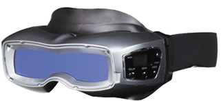
#PN PL-F-S-PPE
Description: Auto-Power On. 327g, Sensor : Photo. One CR2450 Lithium battery /1000h, Light state DIN #3. Dark State DIN #13. Switching light to dark state speed :1/25,000 Sec. Class 1 in all European certification (CE) EN379. Optical tests: Refractive Power / Diffusion / Uniformity / Viewing angle.
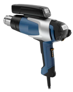
PN# PL-A-ST-HG
Description: 50°C – 620°C (120 - 1150F) adjustable in 6°C (10F) increments. Airstream three settings 110L/min, 110 - 230L/min, 170 – 370L/min (4 cfm, 4-8 cfm, 6-13 cfm). Motor lifetime: 600h. Ceramic heating element. Fits 1.34" Standard nozzles. 1600W @ 120v and 2200W @ 230V. Temperature on LCD display. 0.9kg.
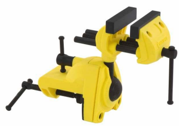
PN# PL-A-VB
Description: Multi Angle Vise, Large C Clamp, Ball Jointed, 3" Jaw Opening, 360° Rotation. Size 19.99 x 8.41 x 21.49 cm; 1.56 Kg. Jaw width 3" or 76.2 mm. Jaw opening 3" or 76.2 mm. Attaches to work surfaces up to 60 mm (2 3/8") thick
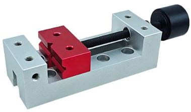
PN# PL-A-VS2
Description: Mini square Vise 122 x 40 x 30mm (4.80" x 1.57" x 1.18"), Clamping jaw: 40 x 15mm (1.57 x 0.60’’). Jaw max opening 50mm (1.97’’). To attach the samples to inspect. Vise placed on any table. Core and handle anodized aluminum. Weight: 0.2kg
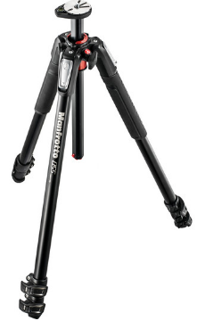
PN# PL-A-TR
Description: Manfrotto Aluminum Tripod: Load: 19.8 lb / 9kg , Max Height: 66.9" / 170cm, Minimum Working Height 3.5" / 8.9 cm, Folded Length: 24" / 61 cm, Leg Sections: 3. Quick Power Leg Locks, versatile 90° centre column mechanism that can be extended horizontally, vertically (normal) or vertically reversed upside down. Rotating Bubble Level. Head Mount 3/8"-16 male Screw. Please add 5/8" Stud Adapter for flash and halogen. Weight: 5.5 lb (2.5 kg). Package Weight: 6.5 lbs (2.9kg)
PN# PL-A-H
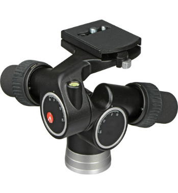
Description: Advanced Geared Head & QR Plate for fine very accurate and quick adjustment. Head weight 3.53 lb / 1.6 kg. Load Capacity of head 16.5 lb / 7.48 kg. Mounting Screw 1/4"-20 Male, 3/8"-16 Male. Lateral Tilt -90° to +30°, Vertical Tilt -30° to +90°, Panning Range 360°. Package weight 4.6lbs (2.1kg)
PN# PL-A-SA
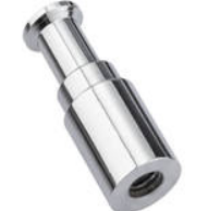
Description: Female Threaded 3/8" to Male 5/8" Stud Adapter - 50mm Long (to attach flash or halogen heating from a 3/8 male thread). Top: 5/8'' (16mm) stud. Bottom 3/8'' thread female.
PN# PL-A-A
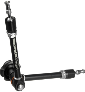
Description: Manfrotto Friction / Articulated Arm: Features a 5/8" stud at one end for supporting heads (halogen or flash) and a fitting for Manfrotto clamp socket or 3/8" thread (e.g., tripod top) or a 5/8’’ receptor at the other end. Allows precise positioning within a spherical volume. Capacity: 6.6 lbs (3 kg). Length: 20.87 in (53 cm). Weight: 2.4 lbs (1 kg)
PN# PL-A-C
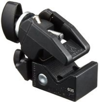
Description: Clamps designed for use with articulated arms. They can be attached to one side of the arm to secure it against round or square surfaces, ranging from 0.5 to 2.1 inches thick, such as tripod legs or table platforms. Alternatively, the clamp can be fixed to the other end of the arm to grip and position a sample for inspection. Package weight: 1.15 lbs (0.52 kg).
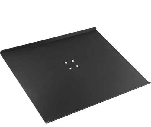
PN# PL-A-TP22
Description: Table platform to be mounted on tripod, to support small samples to inspect. Non-Reflective black Finish. Aluminum. 22 x 16" (56 x 40cm) Surface. 30 lb (13.5 kg) Max. Load Capacity. Secures to 5/8" Stud or 1/4"-20 or 3/8" Tripod Mount. 3.5 lb (1.6 kg). Package weight 5.1lbs (2.3kg)
PN# PL-M-S-VC
Description: Voltage Converter and Regulator: 5KVA stabilizer/transformer converting 110/120V to 220/240V or vice versa (50Hz/60Hz). Regulates fluctuating input voltage from AC 75V-130V or 180V-260V to output voltage: AC 110V +/-4% and AC 220V +/-4%. Meter displaying the output voltage. Two universal outlets for 220V compatible with most countries' plugs, three 110V outlets for 2 or 3 pins USA plugs. On/off switch, indicator lamp, protected with a built-in circuit breaker. Dimensions: 39 x 38 x 26.5 cm (15.4 x 15 x 10.4 inches). Weight: 15.8 kg (34.70 lbs)
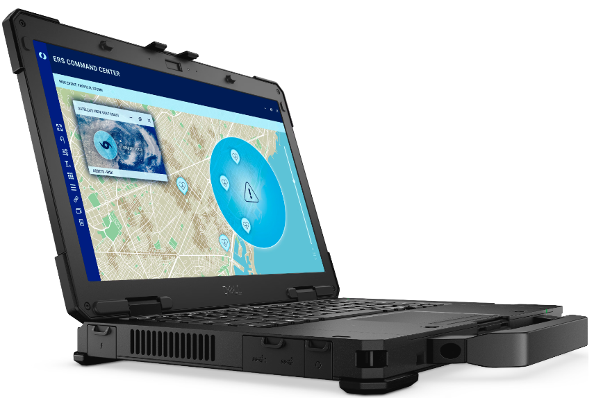
PN# PL-A-PCL1
Description: Dell Pro Rugged 14, MIL-STD-810H certified, Drop-tested from up to 3 feet (1 meter), IP-53 rated for a high degree of protection against dust, dirt and water ingress. Very high-brightness display for clear visibility in any environment.
Specifications: Intel® Core™ Ultra 5 (12 cores, up to 4.3 GHz), Win 11 Pro, 64GB Ram, 2TB SSD, Bluetooth, 14" Touch screen, 1920x1080, Anti-Glare, 1100nit, RGB camera, Passive Pen. H 1.32 in. (33.6 mm) x W 13.38 in. (340 mm) x D 8.66 in. (220 mm)
Starting weight: 4.49 lbs (2.04 kg). Comes with Monitor: Dell 27 inch monitor S2725HS; 4.30 kg; Mouse: Dell Premier Rechargeable Mouse – MS900; Headset: Dell Pro Wired ANC Headset – WH5024
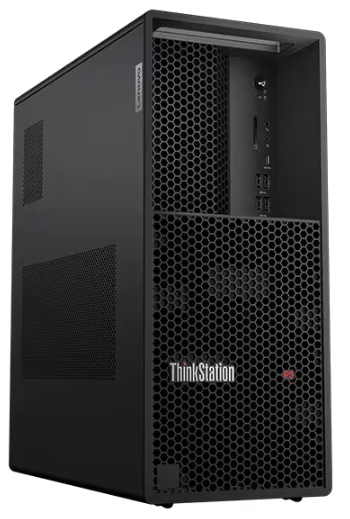
PN# PL-A-PCD1
Description: ThinkStation P3 Tower Workstation (Business Desktops). Intel® Core™ i9-14900K vPro® Processor (E-cores up to 4.40 GHz P-cores up to 5.60 GHz), Win 11 Pro, 128 GB DDR5-4400MT/s ; 2*4=8 TB SSD; 2*6 = 12 TB HDD; Dimensions (H x W x D) 415mm x 180mm x 370mm / 16.3″ x 7.1″ x 14.6″; Weight Starting at 13.61kg / 30.0lbs. Monitor: ThinkVision 23.8 inch Monitor – T24i-30; Mouse: ThinkPad Bluetooth Silent Mouse; Headset: Lenovo USB-A Wired Stereo On-Ear Headset